Halos and Other Optical Effects at Ice Crystals
Introduction
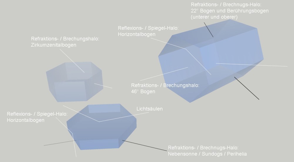
Sun rays are refracted and reflected in various forms by ice crystals suspended in the air. Since ice crystals are significantly larger than the wavelength of light (350-750nm), scattering effects are minimal. Therefore, we can focus on refraction and reflection. While ice crystals come in various forms in nature, hexagonal columns are mainly relevant for optical effects. As the columns align in the air to generate the maximum air resistance during their fall, the length of the columns determines how the crystals orient themselves in the air. If the column is longer than it is wide, it lies sideways; if it is less tall, hexagonal plates lie horizontally in the atmosphere (see figure below).
Ice crystals most commonly occur in high-altitude clouds, known as cirrus clouds. These clouds belong to the third and highest layer. At mid-latitudes, these clouds lie at heights between 8-10km, higher at the equator (up to about 16km), and lower at the poles (up to about 8km). Cirrus clouds appear in various forms, such as Cirrus (fibrous clouds), Cirrocumulus (small heaps), or Cirrostratus (layered clouds). The latter are particularly responsible for optical phenomena because they form very homogeneous layers and extend over large areas of the sky. Since some optical phenomena can occur in a wide angle range, it is necessary for ice crystals to be present in this angle range; otherwise, the optical effect does not occur. That is also the reason why optical phenomena are often only partially visible in the sky.
Ice crystals form at very low temperatures, as commonly experienced in high-altitude flights, with outside temperatures ranging from -40 to -50°C being normal in these altitudes. Due to the partial absence of crystallization nuclei, water droplets can still exist at very low temperatures (up to about -30°C), but cirrus clouds consist exclusively of ice crystals. These crystals grow when there is enough water vapor in the air. The slower the growth process, the more uniform the shapes become. Slow growth is associated with a slow increase in the saturation of water vapor in the air. This occurs, for example, when a warm air layer slides over a cold one, such as during a warm front. Extensive cirrostratus clouds are typical for such fronts and can be identified by optical phenomena (lower clouds consist of water droplets and therefore exhibit different optical effects). Cirrostratus clouds can be so thin that they are not perceived as clouds at all. Only the sky is not as intensely blue. The sun shines more or less dimly through the cloud layer, and only the white ring (a 22° halo) reveals the presence of the cloud. The 22° halo is also one of the most commonly observed halo forms.
Refraction or Diffraction Halo
22° Halo
In the case of a refraction or diffraction halo, the sunlight passes through the ice crystal. It is refracted, or bent, at the entry surface because ice has a higher density (n=1.310) than air. The beam can then exit at the next surface and is refracted a second time upon exit. The deviation from a straight line through the ice crystal is at least 22°. This is a lower limit, and similar to the rainbow, larger angles are possible. Additionally, the beam does not necessarily have to enter in a plane parallel to the hexagonal base of the crystal column, which further increases the angle. Therefore, a long, hexagonal crystal column is at work in the 22° halo, as seen in the image on the far right above. The black line in the upper right here represents the light beam that can create a 22° halo. Since the refractive index depends on wavelength, there is a color separation at the inner edge of the halo, similar to the rainbow. However, this color separation is not always clearly visible. The longer wavelengths, such as red, are seen on the inside, and the wavelengths decrease towards the outside (blue). Afterward, the halo becomes white because all colors are present here simultaneously and mix additively to form white. Therefore, the halo is not visibly limited on the outside, but the inner boundary is clearly visible. The halo can also be generated not only by sunlight, as shown in the image below with the moon as a light source (or sunlight reflector).
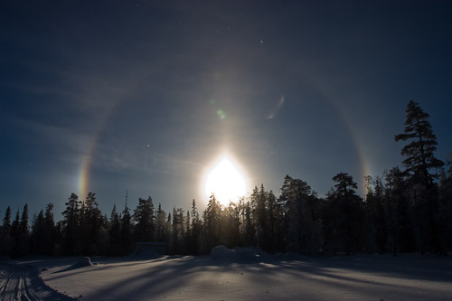
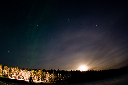
Below is a simulation using the HaloSim tool by L. Cowley & M. Schroeder. In this simulation, only hexagonal ice columns were assumed, with a length twice the width and randomly distributed in the air.
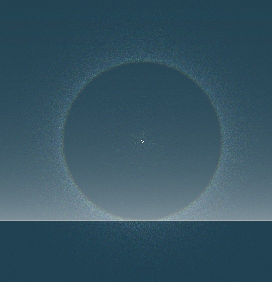
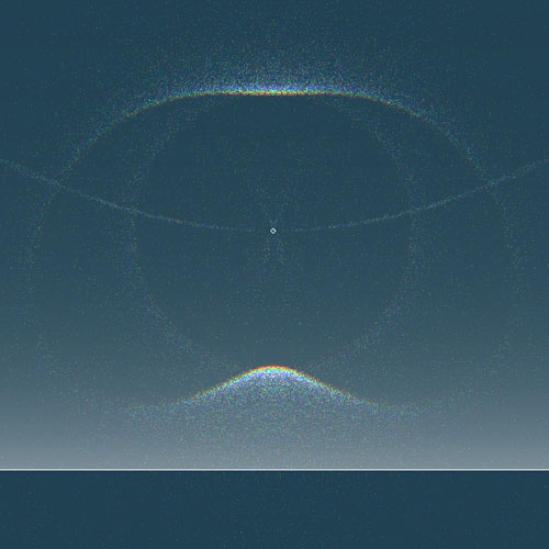
By the way, only crystals that are reasonably aligned in a parallel manner contribute to the halo, meaning they are floating with their optimal position for maximum air resistance toward the ground (they can be held at the same height by upward-flowing air currents). However, if the majority of crystals are optimally aligned, a higher percentage of crystals contribute to the halo. This can lead to the formation of an additional tangent arc, also known as a touch arc. Usually, only its upper part is visible. The tangent arc is formed differently depending on the sun's elevation angle (see images below). At sun elevations above 30° above the horizon, a closed arc may become visible, and the tangent arc may rejoin the 22° halo in the lower part. The simulations shown below include 25% plates with a length-to-width ratio of 1:2, in addition to the ice crystals used above. Also, the orientation of the ice crystals was limited to +/-3 degrees.
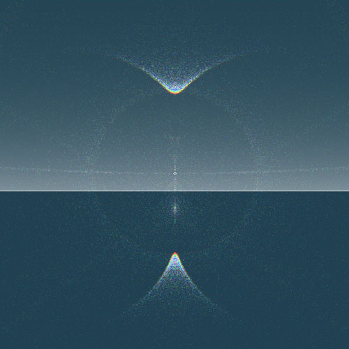
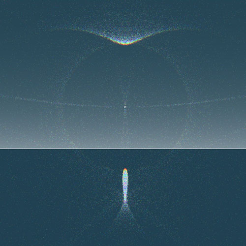
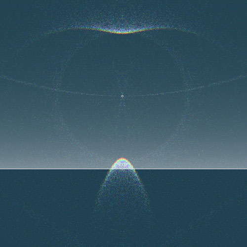
Parhelia
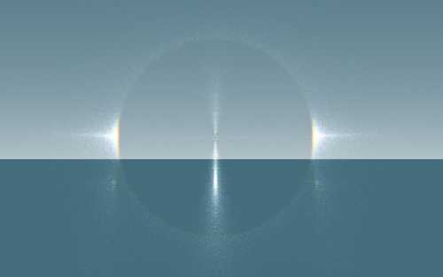
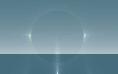
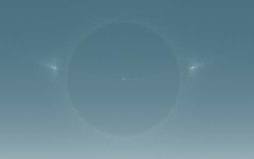
Another frequently visible refraction phenomenon is parhelia, also known as sundogs. Sundogs appear at a low sun angle on the 22° halo and are located at the same height above the horizon as the sun itself. Sundogs are generated by thin, six-sided plates, as shown in the image below on the bottom left. The dark beam again indicates the one responsible for creating the sundog. Since the plates also align themselves to maximize their air resistance, they float in the air with their base parallel to the ground, just as shown in the illustration. Therefore, sundogs are only visible to the right and left of the sun. However, color separation can usually be observed much better in sundogs than is the case with the 22° halo. Depending on how the crystals are distributed in the air, a sundog may be the only phenomenon to form.
As the sun rises, sundogs move away from the 22° halo, so they are no longer on the ring. In the transition phase, the two phenomena are still optically intertwined, but you can already see the significantly outward-shifted position of the sundogs (see the image below of the Meiringen display).
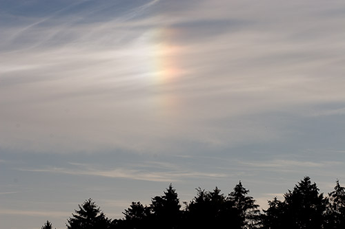
In the case of sundogs, the longer wavelengths are also on the inside, so you see red on the inside, then green, and then blue. The effect, double refraction, is the same as in the 22° halo. In the photo above, the sun is to the right of the sundog.
For the simulations below, only hexagonal plates with a width/length ratio of 1:5 were assumed.

46° Halo
There is another way for a light beam to enter the ice crystal, namely through the base and then out to one of the side faces. In the image above, this is shown on the upper, right-lying ice column. The beam enters on the hexagonal front and exits on the right side. The deflection angle here is 46°, and it also occurs through double refraction. Accordingly, the halo arc produced by this is called the 46° halo. This halo effect is much rarer. Because of its size, it is understandable that it is rarely seen in its entirety, as a so homogeneously formed ice cloud over such a large area of the sky is seldom encountered.
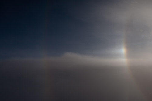
For the simulation below, only hexagonal ice columns with a width/length ratio of 4:5 were assumed.
120° Sundog
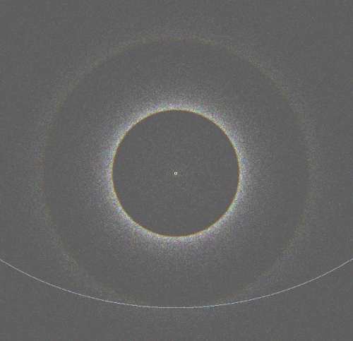
A combination of refraction and reflection occurs in the case of 120° sundogs. A beam enters at the top of a relatively thick plate, is reflected on an inner side, and then exits at the bottom of the plate. Since the beam path involves a reflection that is not very effective, 120° sundogs are much less visible than perihelia, or "normal sundogs" (see above). Moreover, relatively thick plates seem to be relatively rare; in any case, 120° sundogs are rather infrequently observed. The 120° sundogs lie on the horizontal circle (see below).
Circumzenithal Arc
The circumzenithal arc also occurs through the same refraction path as the 46° halo, but here, thicker plates lying horizontally are at work. This scenario is depicted in the first image at the top left. The circumzenithal arc is very rarely visible; apparently, thicker plates are seldom encountered. The lower image shows several phenomena at the same time. If you move the mouse over the image, the individual effects are labeled.
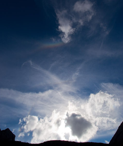
Multiple optical effects in one display: 22° halo, sundog (clearly separated from the 22° halo
here),
46° halo, upper tangent arc, and circumzenithal arc
Image |
Image with
description
Move the mouse over the text above to display the description
Mirror Halos
Horizontal Circle
Light can not only penetrate the ice crystal; it can also be reflected on its surface. This effect is responsible for the horizontal circle. Light is reflected on vertical crystal surfaces. However, since the crystals can be rotated about the vertical axis relative to each other, the reflection occurs not only at one point but along a circle parallel to the horizon, i.e., a horizontal circle. This circle passes through the sundogs; in older reports, it is therefore also called the sundog ring. In the photo below, the circle is vaguely visible, intersecting the 22° halo at the sundog (which may not be the case depending on the sun's elevation, see above).
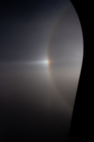
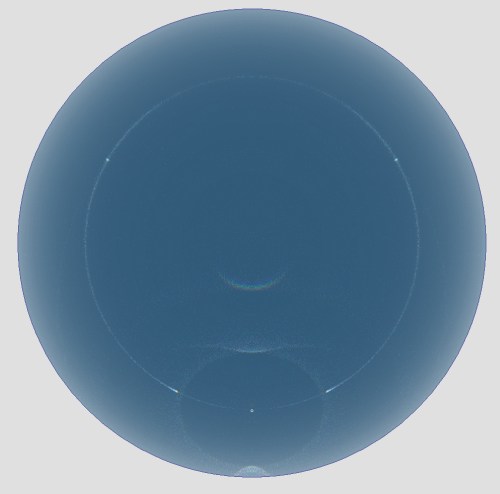
The simulation below shows, in addition to the 22° halo and the sundogs, the horizontal circle, the upper and lower tangent arcs, and the circumzenithal arc. Four different crystals were used for the simulation.
Light Pillars
Far more frequently visible than the horizontal arc are light pillars above and below the sun. In these phenomena, sunlight is reflected on the upper or lower side of the crystal, i.e., on the surfaces that are aligned parallel to the Earth's surface. Since the crystals do not lie exactly parallel but can oscillate a bit around this position, many crystals can contribute to this effect. In the light pillar above the sun, sunlight is reflected on the underside of the crystals, while in the light pillar below the sun, it is reflected on their upper side.
In the simulation below, crystal plates with a width/length ratio of 3:1 in two layers (tilted 3 and 8°) were assumed.
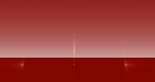
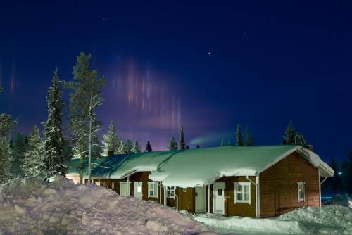
However, light pillars can not only be generated by the sun but also by lamps directed towards the sky or by light reflected upwards by a reflective (e.g., water) or white (e.g., snow) surface.
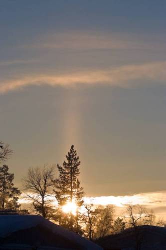
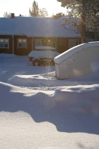
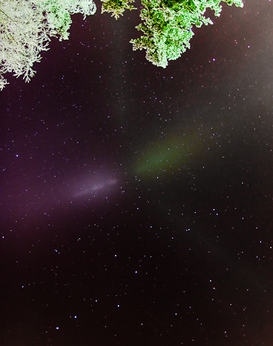
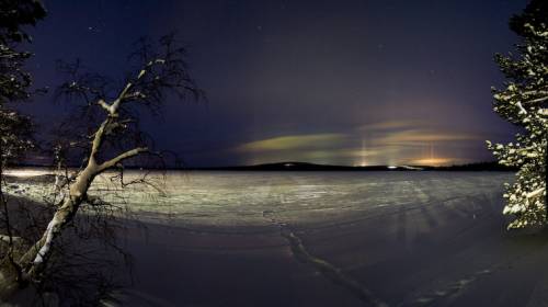 light pillars from lamp light reflected on the snow (Muonio, Finland, February 2007)
